Does not use mechanical coil operated power
relays which consume high battery power, uses electronic Mosfet
switching to control up to 4 switched outputs.
Designed to be used in low power portable
battery systems. Built and tested in the UK.
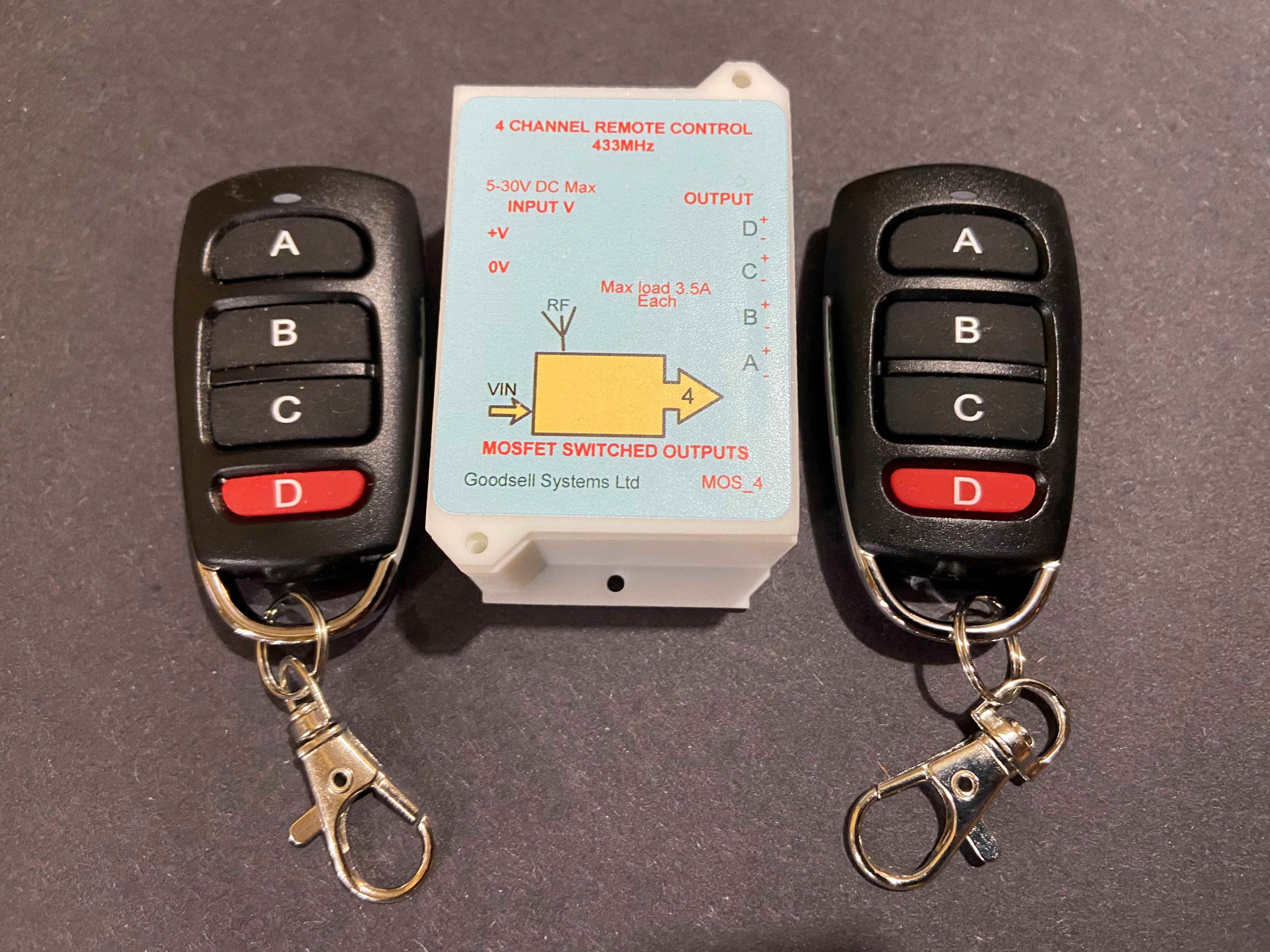
Will operate with any input voltage from 5V DC
to 30V DC.
Operating temperature range, -20° to + 75°C.
Operates
over the 433 Mhz
Radio
control frequency signal transmission
band.
You
can remotely control each output via the 4 channel transmitter key
fob, two fobs are supplied as standard, up to 20 key fobs may be
‘paired’ to the receiver unit.
The
receiver module can be controlled to within 50 meters, in open
area. The RF chip used is the learning code chip EV1527 which makes
the system very secure.
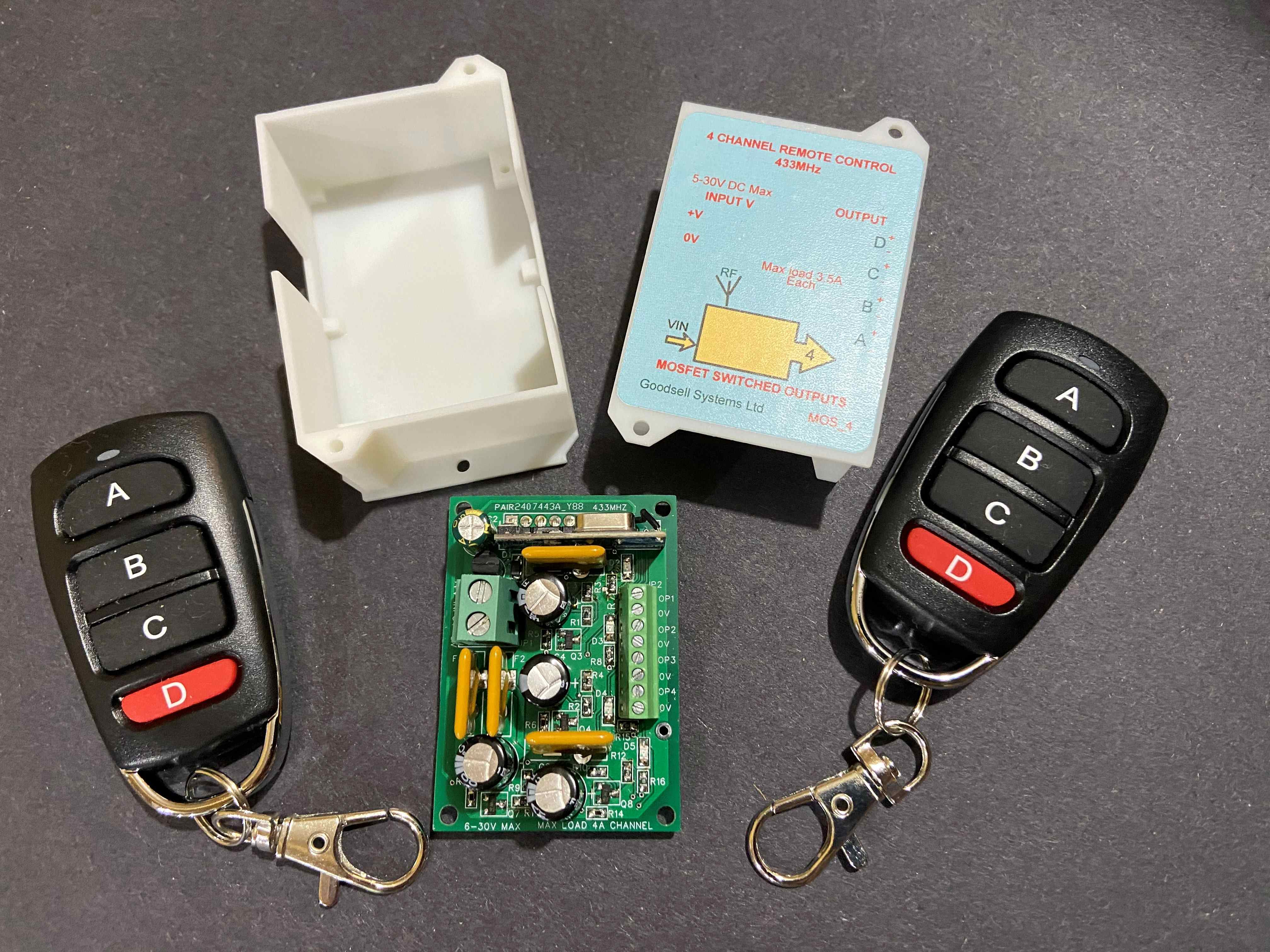
Each output switches the +V input rail to it’s
output terminal and uses the common input 0v as it’s
return.
Each output can source up to 3.5 Amp continuous
current (dependant upon input voltage level, see ‘safe area’
illustration below).
Each output is individually protected by a self
resetting electronic fuse. There are 4 LEDs mounted on the PCB that
indicate if that channel is ON or OFF.
The maximum current through the system with all
4 outputs ON, is 12 Amps total.
The standby current is only 6 mA, even with the
4 outputs switched ON (but no load current).
Two remote transmitter fobs are included, both
are ’paired’ to the control unit and are fully tested before
leaving the factory, also each of the 4 outputs are tested at full
power to ensure correct operation. Batteries are included within
the TX fob units.
The RF
receiver is extremely easy to set up and reset. There are 3
operating modes (momentary/toggle mode & latching mode) that
can be configured. Momentary mode is the default mode
when shipped.
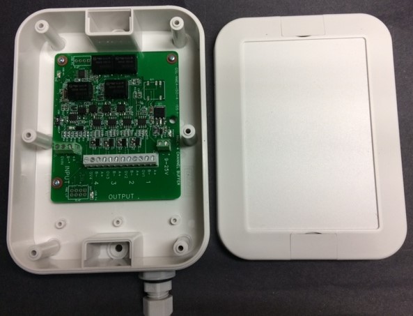
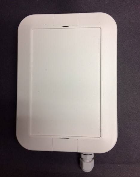
The receiver module is housed within a small
plastic enclosure, 68 x 45mm, with internal heat sinking, no
external aerial is required.

Operating
mode.
The remote control
fobs supplied have already been ‘paired’ to the receiver module and
set for ‘Momentary’ mode. If you require ‘Toggle’ mode or ‘Latched’
mode you will need to delete the memory within the RX module
first.
Press the ‘learning’
button 8 times to clear the memory, the LED will flash 3 times
after, indicating the memory is clear and you may now select one of
the modes below.
Momentary
Mode:
Set-up.
Press the learning
button on the RX board ‘once’.
Wait 3 seconds for
the LED to stabilise ON.
Press button ‘A’ on
the remote control.
All 4 buttons will
now operate in ‘Momentary-mode’ individually.
Toggle Mode:
Set-up.
Press the learning
button on the RX board ‘twice’.
Wait 3 seconds for
the LED to stabilise ON.
Press button ‘A’ on
the remote control.
All 4 buttons
will now operate in ‘Toggle Mode’ individually,
Press button once to
turn ON the channel, press same button again to turn OFF the
channel.
Latched
Mode:
Set-up.
Press the learning
button on the RX board ‘3 times’.
Wait 3 seconds for
the LED to stabilise ON.
Press button ‘A’ on
the remote control.
All 4 buttons will
now operate in ‘Latched Mode’.
Press the ‘A’ button
once to turn ON channel A, press button ‘B’ to turn OFF channel ‘A’
and at the same time this will turn ON channel ‘B’.